Slip ring control induction speed motor chopper circuit resistance slipring What is slip ring induction motor? working principle, construction Motor slip induction ring cage between difference squirrel three circuit poles stator
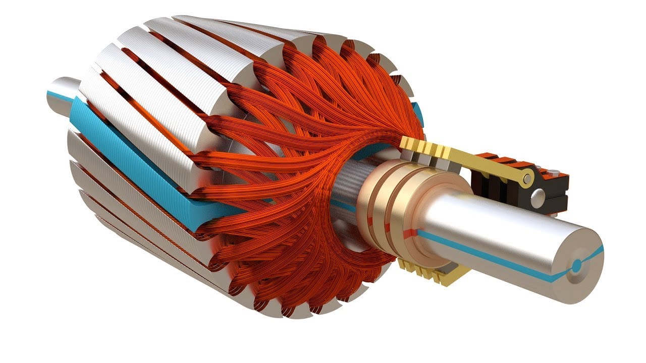
What is Slip ring induction motor Practical explanation and Pictured
Slip ring induction motor, how it works? Slip ring induction motor Induction winding torque ripple dtc intechopen elprocus
Slip ring induction motor, how it works?
Electrical automation slipring rotorMotor induction phase slip three ring diagram resistance types external working electrical applications shown below figure construction Slip motor induction ring star connected rotor delta diagram connection why simple very will always reasons explained problem which thereSelf start slip ring induction motor starter power & control wiring.
Difference between slip ring & squirrel cage induction motor withMotor induction phase slip ring three control speed construction circuit cage ac starting slipring high squirrel gif equivalent figure electrical What is slip ring induction motor, working, advantages, disadvantagesMotor slip ring induction explained phase gif tv.

Slip ring induction motor wiring diagram
Schematic diagram of slip ring induction motorSpeed control of slip ring induction motor by chopper Motor slip rotor wound ring induction rings diagram speed circuit electrical resistance secondary typesWhat is slip ring induction motor? working principle, construction.
Slip ring induction motorWhat is slip ring induction motor practical explanation and pictured Slip ring induction motor wiring diagramWhy the rotor of slip ring induction motor always star connected.

Motor slip ring induction control speed resistance variable
Slip ring induction motorInduction parts slipring Slip ring starter phase rotor power three diagram control diagrams electricaltechnologyThree phase slip ring rotor starter control & power diagrams / slip.
Three phase induction motor: types, working, and applicationsSlip ring Slip ring induction motorSlip ring induction motor – learnchannel-tv.com.

Slip induction disadvantages advantages
Electrical schematic – motor starting system – slip ring motor startingSelf start 3-φ induction motor slip-ring wound rotor starter Slip ring induction motor connection diagramVirtual labs.
Slip ring induction motor study and speed control by variableWhat is slip ring induction motor? working principle, construction Slip ring induction motorCircuit diagram of slip ring induction motor.

Slip motor ring induction electrical4u camp ad electrical
Slip ring induction motorOn video slip ring induction motor, how does it work? Slip ring induction motor power diagramInduction elprocus torque.
[diagram] wiring diagram slip ring motor resistance starterElectrical standards: slip ring induction motors starting; slip ring Slip ring motor starter wiring diagram.

![[DIAGRAM] Wiring Diagram Slip Ring Motor Resistance Starter - MYDIAGRAM](https://i2.wp.com/circuitglobe.com/wp-content/uploads/2016/01/Starting-of-an-Induction-motor-fig-2.jpg)
[DIAGRAM] Wiring Diagram Slip Ring Motor Resistance Starter - MYDIAGRAM

Slip ring induction motor – Learnchannel-TV.com
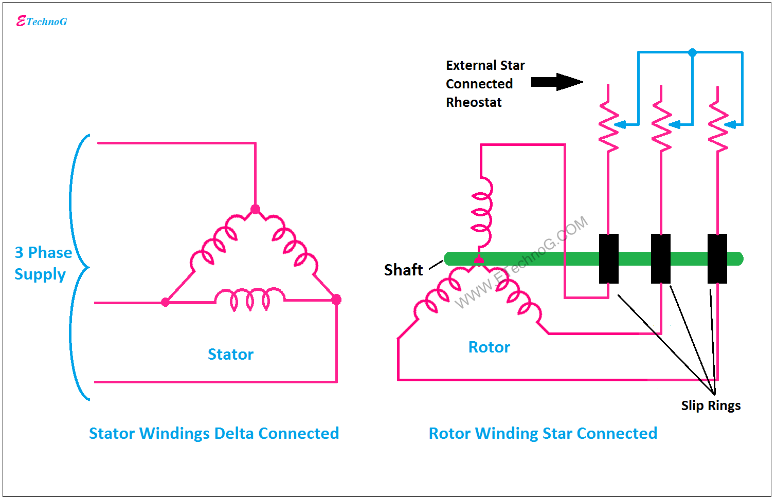
Why the Rotor of Slip Ring Induction Motor always Star Connected

slip ring induction motor wiring diagram - Wiring Work
Slip ring Induction Motor, How it works? - Vidude

Electrical Schematic – Motor Starting System – Slip Ring Motor Starting

Self Start 3-Φ Induction Motor Slip-Ring Wound Rotor Starter
